
TURNING TOOLS
Boring Bars
Internal turning and boring toolholders for CNC lathes and conventional lathes.
Select a boring bar by insert shape, minimum bore diameter, shank size, tool hand, approach style and required overhang. Correct holder selection helps improve rigidity, chip control, dimensional stability and surface finish in internal turning.
Choose the Right Boring Bar
Start with the bore geometry and selected insert, then confirm holder size and machine clearance.
Match the holder to the required insert family, such as CCMT, DCMT, VBMT or other compatible ISO insert geometry.
Confirm that the holder head and insert can enter the required bore without interference.
Use the shortest practical overhang and the largest suitable shank diameter to reduce vibration and deflection.
Select right-hand or left-hand configuration according to feed direction and internal machining setup.
Match boring bar diameter to the machine holder, turret or boring-bar sleeve while maintaining sufficient stiffness.
Confirm whether the application requires general boring, internal profiling, facing, finishing or shoulder access.
Rigidity Matters
Boring bars operate with greater overhang than most external turning holders, so stiffness is critical to stable machining.
Keep the bar extension as short as practical whenever component geometry allows.
Select the largest shank diameter that can safely enter the bore and fit the machine holder.
Longer overhang increases deflection and vibration risk, especially during heavier cuts.
How to Read a Boring Bar Code
Holder designations identify the clamping method, insert shape, holder style, clearance requirement and tool hand.
Screw-type insert clamping designation.
C-shape, 80° diamond insert.
Holder configuration and approach-style designation.
Clearance-angle compatibility designation.
Right-hand holder designation.
Exact holder-code interpretation depends on the ISO designation and manufacturer series. Always verify the full holder and insert compatibility before ordering.
Match the Holder to the Application
Start with a general-purpose boring bar compatible with the required insert shape and bore diameter.
Use holder and insert geometry that provides sufficient access around internal contours and shoulders.
Prioritise rigidity, low cutting force and suitable insert geometry for stable surface finish.
Minimum bore diameter becomes the primary constraint; check holder-head and insert clearance carefully.
Browse Boring Bar Series
Compare available boring bar styles, insert compatibility, sizes and pricing below.
-

PCLNR
Price range: $165.00 through $605.00 exc. GST -
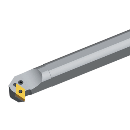
PDPNR
Price range: $330.00 through $440.00 exc. GST -
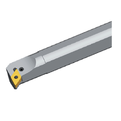
PDUNR
Price range: $110.00 through $330.00 exc. GST -
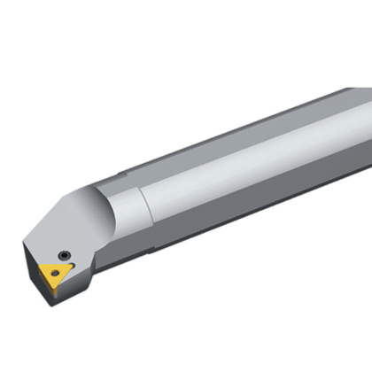
PTFNR
Price range: $198.00 through $440.00 exc. GST -

PWLNR Internal Turning Boring Bar – WNMG Inserts
Price range: $90.00 through $190.00 exc. GST This product has multiple variants. The options may be chosen on the product page -

SCLCR Internal Turning Boring Bars – CCMT Inserts
Price range: $80.00 through $180.00 exc. GST This product has multiple variants. The options may be chosen on the product page -
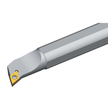
SDQCR
Price range: $88.00 through $440.00 exc. GST -

SDQPR
Price range: $100.00 through $120.00 exc. GST -
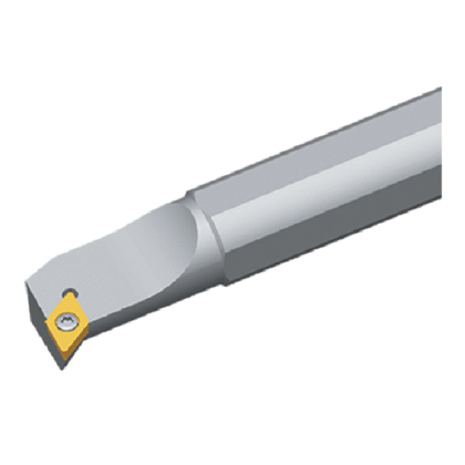
SDUCR
Price range: $88.00 through $440.00 exc. GST -
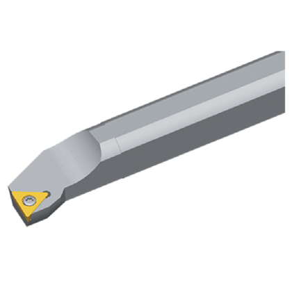
STFCR
Price range: $88.00 through $330.00 exc. GST -
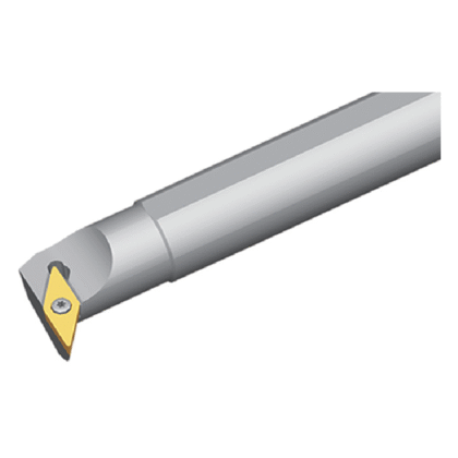
SVUCR
Price range: $110.00 through $264.00 exc. GST